Central Rod
2026-01-16
About the fabrication and installation of the Central Rod…
Introduction
This section covers the manufacturing and installation of the central rod. First, it’s important to note that the central rod is closely related to the diameter of the chamber.
Therefore, the diameter, length, and perforation steps of the central rod vary depending on the size of the chamber.
Key factors
- Number of layers of air nozzles
- Number of air nozzles per layer
- What metal pipe is suitable for the Central Rod?
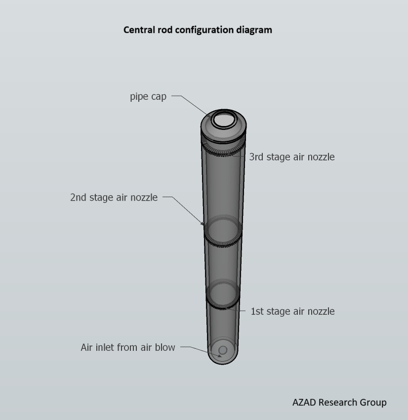
Composition of the Central Rod
The central rod consists of a cap, a body, a three- or four-stage air nozzle, and an air intake at the bottom.
Air nozzle
The air nozzles perforated in each layer can be perforated in two stages, as shown in the image. This is to facilitate heat circulation within the chamber. Alternatively, the perforation angle of the air nozzles may need to be adjusted.
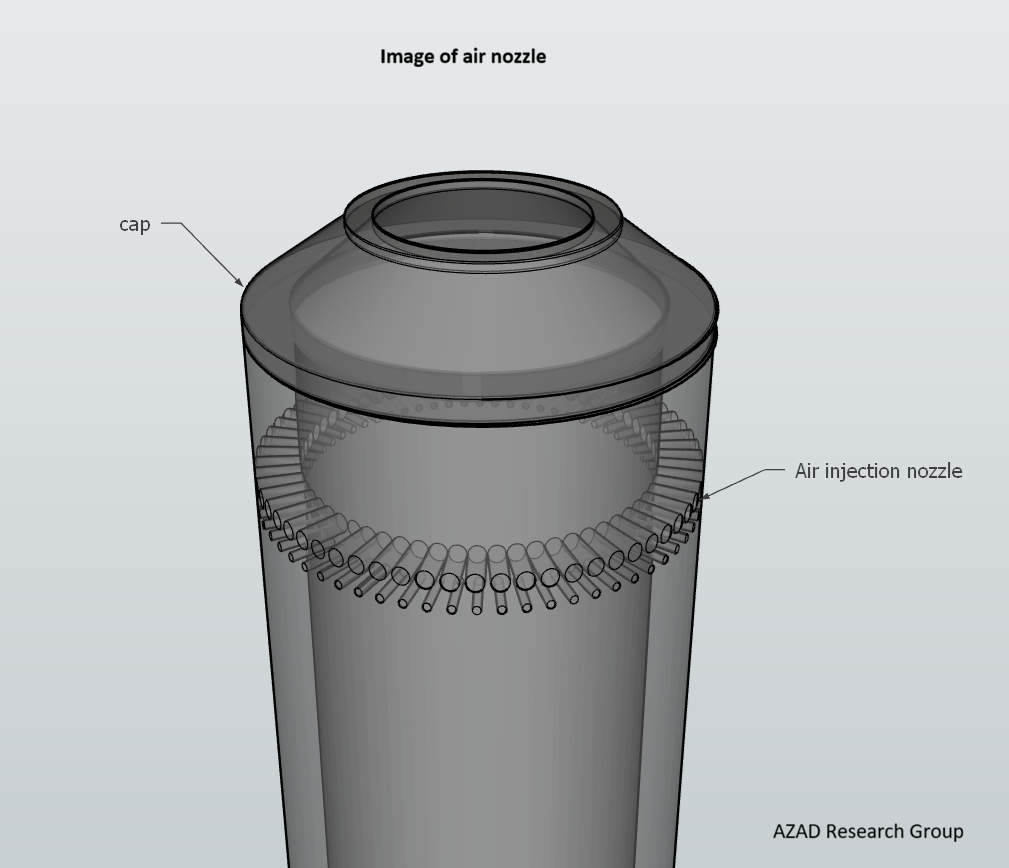
Number of air nozzles per stage
The number of air nozzles per stage and their height vary depending on the diameter of the central rod, which varies depending on the size of the chamber. This should be standardized through field testing for each chamber type.
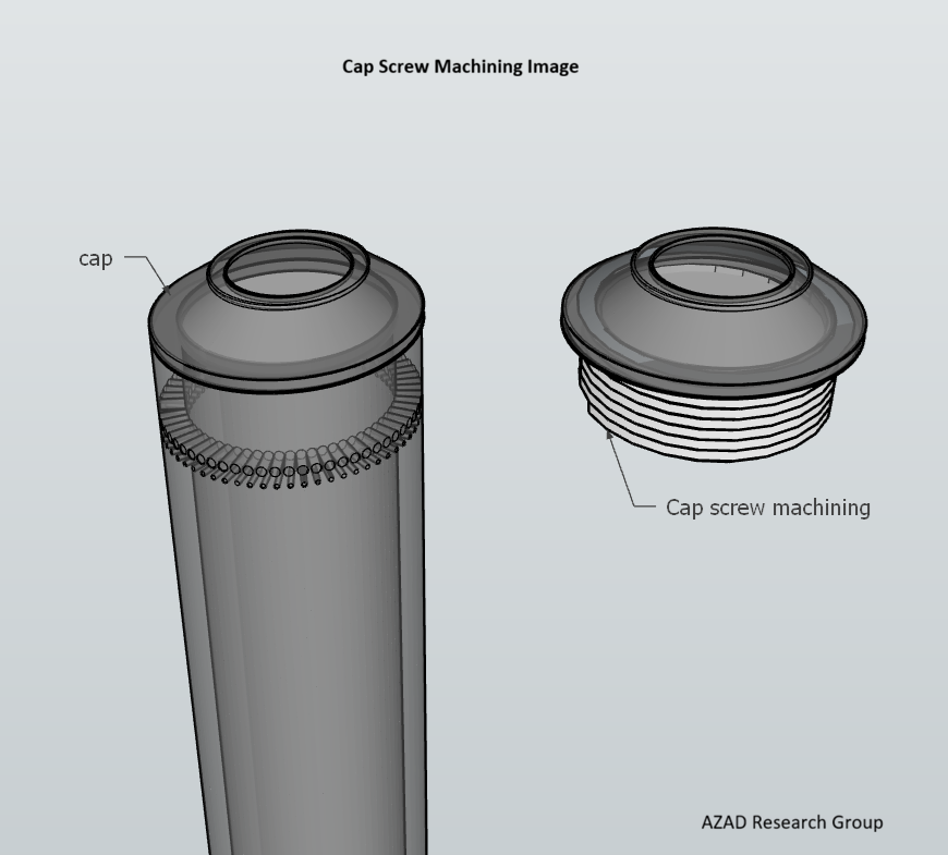
Cap screw machining
The cap is necessary for cap screw machining when opening the cap to clean the inside of the rod or repair a clogged air nozzle.
Metal material of the central rod
The metal material of the central rod is susceptible to thermal oxidation due to the high temperatures generated during thermal treatment (average temperatures exceeding 850 degrees Celsius).
Therefore, the pipe must be made of a strong metal material capable of withstanding the high temperatures associated with thermal oxidation. However, a cost analysis must be conducted to compare it to using multiple metal pipes made of conventional metal.
Note
The posts on this blog will be continuously updated.
Last update: 2026-02-07